The last major project we wanted to complete before moving aboard full time was to convert the original icebox into an efficient fridge/freezer. Some early Freeport's were delivered with an overflow type fridge and freezer from new (possibly as a standard feature or maybe an up-charge option?) but Circe only had a factory-built icebox. It was huge, over 10 cu. ft., but poorly insulated, with only 1.5 - 2 inches of spray foam on the outside of the molded FRP box and four small, unsealed, loose fitting hatches on top. It had been adequate for holding blocks of ice for a few days, but nothing more. Sometime in the past a Technautics 'Cool Blue' compressor and a big holding plate had been installed in the ice box but nothing had been done to improve the insulation or block the melt-water drain. Consequently the compressor was running almost continuously, working way too hard, and using tremendous amounts of power to keep the big box cool. Shortly before we bought the boat, not surprisingly, the original compressor had failed and the PO had installed a new one but, unfortunately, he didn't do anything about the insulation.

First things first.....while working on the icebox we put a small Kenmore dorm fridge on board so that we could still have some home comforts......while we're at the dock anyway. We can't enjoy a Tanqueray and Tonic without some ice. We didn't want a cooler cluttering up the cabin and its a long trek to the ice machine!
We had previously seen how some Freeport and other similar icebox designs had been successfully converted to fridge/freezer combo's by lining the interior of the icebox with additional, high R-value insulation, resulting in a much smaller but much more efficient unit. So, we decided that we also would go that way......no point in re-inventing the wheel! If we had been starting the conversion from scratch we would probably have gone with a Frigoboat chiller, which seems to have very good reviews, but with the new Cool Blue compressor and big holding plate already in place we couldn't justify the additional expense. We aren't planning any tropical travels so, in a properly insulated box, the Technautics system will be more than adequate for our needs.

Here is the original molded FRP factory icebox with the big, zero degree (Technautics) holding plate. The steps in the side walls of the box were for removable shelves and the centre slot in the floor is for a teak divider to stop the ice blocks from moving around too much. (Can you even get ice blocks any more?)
Even with such a powerful holding plate, the poor insulation of the box caused the compressor to run almost continually. In addition to the lack of insulation the icebox drain hole was still wide open, spilling cold air from the box as fast as the plate was chilling it. Items in the box were just barely keeping cool, with no hope of ever freezing anything!

Even with such a powerful holding plate, the poor insulation of the box caused the compressor to run almost continually. In addition to the lack of insulation the icebox drain hole was still wide open, spilling cold air from the box as fast as the plate was chilling it. Items in the box were just barely keeping cool, with no hope of ever freezing anything!

Here is the almost brand new Technautics 'Cool Blue' compressor in the Port Cockpit Locker. It is solidly mounted on a rugged bracket but it will be moved slightly for better pipe runs into the re-designed and re-insulated icebox.


Here is the holding plate after we cut the lines and drained the eutectic solution from it. We will check with Technautics to get some advice on how to fix it.

After all the strife with the holding plate we finally got around to removing the counter top for improved working access. Our new design will have two sealed hatches, one each to get into the fridge and freezer, instead of the four unsealed ones supplied by the factory.


Getting the counter off was a real battle. It was heavily glued and screwed (cross screwed in several places) so we ended up using the Dremel Multi-Max to cut it out piecemeal.

We first tried the conventional method of peeling the Formica off to access the counter-top securing screws, but when we found the cross screwing and gluing it became clear we wouldn't get a 'sanitary' removal so the pry bar came out and we got a bit more 'creative'!


Scalpel, Forceps, Dremel....... Sectioning the old counter with the Multi-Max to make removal easier.

The Dremels are really versatile. Here is the Cordless Rotary in trimmer/router configuration. This cut is where we will splice in the new counter.

Here is the box with the first piece of the counter removed. As can be seen, even with the screws removed and the counter sectioned, the adhesive used by the factory was bionic! The pieces of counter still had to be literally torn off with the pry bar!

What a mess....will we ever be able to get a functional fridge/freezer from this shambles? After a 2 day slog we finally got the counter off and everything cleaned up.


While all of this was going on we had sent the holding plate back to Technautics for a check-out, re-charge with eutectic solution and to have the correct Aeroquip fittings installed. We also ordered new supply lines and new retaining blocks.
http://www.technauticsinc.com
The two photos below show the refurbished holding plate back from Technautics, along with the new pipework and fittings. A big thanks to Randy Simkins at Technautics for all his help on this project.


We wanted to break the gloss on the inside of the box to give a key for the adhesive securing the new insulation sheets. This time the Multi-Max is configured for sanding. This post is turning into Dremel ad!
At this point we were at 'Ground Zero'. From here on we will be building rather than demolishing! The factory icebox had two horizontal steps molded into each side and a vertical groove molded in the front, rear and bottom. The groove held a vertical teak divider to stop ice blocks sliding around, the lower step supported a grate to hold the food items off the ice and the upper step supported a sliding Lexan shelf for more food storage space. We wanted a much simpler, cleaner, flat sided box without all that complexity so we had to get rid of all the grooves and steps. In our experience, fridge contents stored on shelves get thrown about, spilled and damaged, even in a moderate seaway. They seem to do better when bunched together. Another benefit of wedging things together is that they stay colder longer with less power consumption.
After some research we felt that foamed polyurethane planks were the best insulation choice for the highest R-value. In the end however we had to use two different insulation materials, in three different thicknesses, to give us the R-values we wanted while also getting the box shape we wanted.


The Insulfoam polystyrene sheets we chose have a slightly lower R-value than foamed polyurethane but they are more versatile as they are available in a bigger variety of thicknesses. The Insulfoam film is skinned on both sides for moisture protection.

To start things off and give us a flat base we used spray foam to fill the groove in the bottom and edges of the box.

We also used the foam to fill the old icebox drain, the hole for the holding plate pipes (we'll make a new one to suit the new plate location) and all the other small fastener holes. Weird colour on this pic!


We used the old faithful, West System epoxy, to glue things together.

Here are the first pieces of insulation going in on the lower step in the box. This shot and the next one (below) shows how the layering of the thinner foamed polystyrene sheets eliminates the step and flattens the sides of the box.


Here are some of the big 2 inch foamed polyurethane planks going in. The Rube Goldberg bracing was to hold the Thermasheath planks in place while the epoxy cured.

With all the insulation epoxied in place, we checked all the seams, foamed the edges, corners and any small remaining gaps. Finally we were ready for the liner panels. We got the liner panels from our local Lowes. They are available in various colours and textures. we went with an off-white liner with a 'pebbled' texture.


Here are some of the FRP liner panels cut from the templates and ready to be installed in the box.

Liner panels clamped in place while being epoxied into the box.

Box with liners epoxied onto all sides and taping started prior to caulking all the joints.

Taping completed, ready for 3M5200 caulk.

Caulk going in. We chose 3M5200 for its permanence and tenacity in what will be a heavy use area. We don't plan to pull this thing apart....ever!

After the caulk application it was smoothed into corner fillets with a plastic stirring stick.

Caulking finished, tape off, ready for mounting the holding plate and drilling the new hole for plumbing.
 Here is the lower holding plate retainer in place. As supplied by Technautics the grooved retainers were not drilled for fixing screws. We drilled and then counter-bored ours, but they can simply be drilled straight through to suit. We just thought the recessed screws looked cleaner and a bit more professional.

Here we are test fitting the holding plate to establish the positions for the two side retainers.
 All retainers in place and the holding plate securely mounted. With the holding plate in place we established the position for the new access hole for the plumbing and the thermostat wires. Drilling a 1.5 inch diameter hole through 6 inches of liner panel, foam, molded fiberglass, more foam and finally 0.75 inch of plywood was quite a challenge!

We used an improvised extension for the hole saw and went as far as we could from inside the new box. Then we ran an extra long drill bit to extend the pilot hole from the hole saw through to the cockpit locker and finished with the hole saw from the other side.

We knew from the beginning of this project that we would have to slightly re-position the compressor. This was the time! It was blocking access to the locker side of the new plumbing hole, so out it came.

Sometime in the past a PO had taken the time to build a rugged compressor mounting bracket from 3/4 inch plywood, glued and screwed.....it is really solid. We will just reposition it on the bulkhead and maybe paint it if we have time.

Here is the almost new Technautics Cool Blue compressor installed by the PO. We lost most of the gas from it when we cut the pipes to the holding plate so we will have to buy a charging hose and a couple of cans of R-134 when we fire things back up.

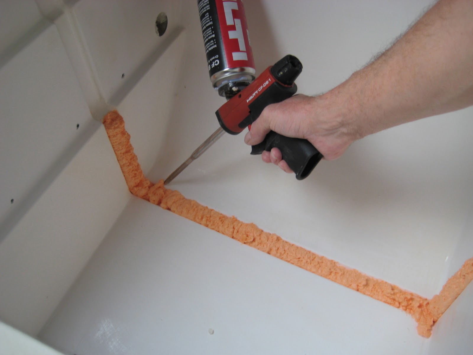
While we were in the locker drilling the new plumbing hole we filled the old one with foam. Gotta love that Hilti foam gun!

The next step was to hook up the holding plate pipework so as to establish the best location for the compressor to suit the new plumbing hole. We also tried some positions for the thermostat bracket (foreground).

With the holding plate pipework in place we played around in the cockpit locker to find the best position for the compressor mounting that gave smooth routing of the pipes.

We modified the compressor mounting bracket slightly, painted it and relocated it for better routing of the pipes and thermostat wires.

Here is another view of the installation with all plumbing and wiring hooked up.
The next step was to build a spill-over divider to create the separate freezer and refrigerator compartments. It took us a while to decide on a design for the divider as there is a lot of conflicting info on the best way to set up the 'overflow' feature. In the end we went with a 1" thick divider, faced with the 090" liner panels, with a 2.5" diameter air drain hole in the bottom and two 1" diameter overflow holes at the top. We made the air drain hole plenty big so that we can 'choke' it down if we find the fridge is getting too cold. Easier than trying to open up a hole that is too small!

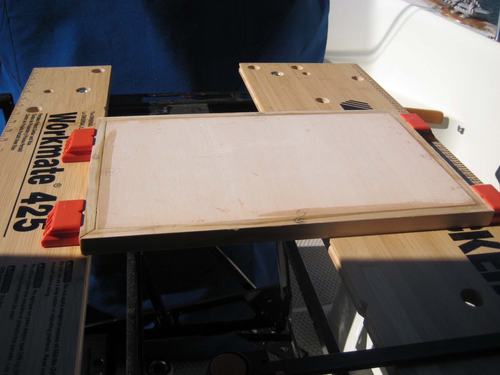
We made a template, cut the foam and then the liner panels to match. This photo shows the foam and liner panel sandwich, 'buttered' on both sides with epoxy.

This shot shows the improvised plywood assembly press we made, clamping everything together while the epoxy cured.

Out of the press and ready for air drain and overflow holes.

The air overflow and drain holes being drilled. (we really must get around to that cap rail varnish!)

To line the holes we used PVC pipe fittings.

The big fitting for the air drain hole needed to be trimmed for length.

All the air flow holes were sealed and the PVC fittings caulked with 5200.
 Here is the finished divider going in for a trial fitting. Somehow we ended up with a bit more of a gap at the top rear edge than planned but nothing that can't be fixed with a little spray foam and some 5200!
(Hey, those who never make mistakes never make anything!)

Here is the divider epoxied in place with the edges sealed with 5200.

We also fitted the thermostat and routed the wires and capillary tube. We will probably fit a solid state thermostat in the future but for now we will use the original, Danfoss electro-mechanical unit.

The next step was to re-charge the system, start up the compressor and run a short test to make sure everything was working properly. We got a couple of cheap digital thermometers and temporarily covered the box with plywood to see what temperatures we were getting.
 Our first, two hour, test gave excellent results. The top numbers are cabin temp, the bottom number on F1 is the fridge side and on F2 is the freezer. We were pleased to see how quickly the freezer side dropped below 32 degrees but the fridge side was still a bit warm because we over-choked the air drain hole a bit. A larger choke is needed, an easy fix.

Here are the different size chokes we tested. The wide open fitting in the divider was 2.5"dia, the small choke (left) was 1" dia. and the intermediate one was 1.5" dia. We will probably go with the 1.5" choke until we can see how the unit performs when both sides are full of foodstuff.

Finally we were ready to start building the new counter top, freezer and fridge access hatches. We started with a template made from 0.25" plywood to get the basic shape down and fix the location of the two apertures for the fridge and freezer hatches.

Once we had checked and proved the template we moved to 0.75" plywood and cut it to match the original counter top that we ripped out at the start of the project.......months ago!

The fridge and freezer apertures were cut to match the template.

We considered putting the new laminate on after the counter top was installed but decided it would be too difficult in such a restricted space. Also, it would be difficult to get the new hatches and their support cleats installed. So, we elected to do everything on the bench (Workmate) and install the finished counter and hatches as a unit, although it will make securing the counter a bit more difficult.

We looked at Wilson Art and Formica laminates and finally chose a Travertine design in Formica. Here we are putting the first strips around the edges of the two access apertures.


Here we are test fitting the holding plate to establish the positions for the two side retainers.


We used an improvised extension for the hole saw and went as far as we could from inside the new box. Then we ran an extra long drill bit to extend the pilot hole from the hole saw through to the cockpit locker and finished with the hole saw from the other side.

We knew from the beginning of this project that we would have to slightly re-position the compressor. This was the time! It was blocking access to the locker side of the new plumbing hole, so out it came.

Sometime in the past a PO had taken the time to build a rugged compressor mounting bracket from 3/4 inch plywood, glued and screwed.....it is really solid. We will just reposition it on the bulkhead and maybe paint it if we have time.

Here is the almost new Technautics Cool Blue compressor installed by the PO. We lost most of the gas from it when we cut the pipes to the holding plate so we will have to buy a charging hose and a couple of cans of R-134 when we fire things back up.

While we were in the locker drilling the new plumbing hole we filled the old one with foam. Gotta love that Hilti foam gun!

The next step was to hook up the holding plate pipework so as to establish the best location for the compressor to suit the new plumbing hole. We also tried some positions for the thermostat bracket (foreground).

With the holding plate pipework in place we played around in the cockpit locker to find the best position for the compressor mounting that gave smooth routing of the pipes.

We modified the compressor mounting bracket slightly, painted it and relocated it for better routing of the pipes and thermostat wires.

Here is another view of the installation with all plumbing and wiring hooked up.
The next step was to build a spill-over divider to create the separate freezer and refrigerator compartments. It took us a while to decide on a design for the divider as there is a lot of conflicting info on the best way to set up the 'overflow' feature. In the end we went with a 1" thick divider, faced with the 090" liner panels, with a 2.5" diameter air drain hole in the bottom and two 1" diameter overflow holes at the top. We made the air drain hole plenty big so that we can 'choke' it down if we find the fridge is getting too cold. Easier than trying to open up a hole that is too small!

We made a template, cut the foam and then the liner panels to match. This photo shows the foam and liner panel sandwich, 'buttered' on both sides with epoxy.

This shot shows the improvised plywood assembly press we made, clamping everything together while the epoxy cured.

Out of the press and ready for air drain and overflow holes.

The air overflow and drain holes being drilled. (we really must get around to that cap rail varnish!)

To line the holes we used PVC pipe fittings.

The big fitting for the air drain hole needed to be trimmed for length.

All the air flow holes were sealed and the PVC fittings caulked with 5200.

(Hey, those who never make mistakes never make anything!)

Here is the divider epoxied in place with the edges sealed with 5200.

We also fitted the thermostat and routed the wires and capillary tube. We will probably fit a solid state thermostat in the future but for now we will use the original, Danfoss electro-mechanical unit.

The next step was to re-charge the system, start up the compressor and run a short test to make sure everything was working properly. We got a couple of cheap digital thermometers and temporarily covered the box with plywood to see what temperatures we were getting.


Here are the different size chokes we tested. The wide open fitting in the divider was 2.5"dia, the small choke (left) was 1" dia. and the intermediate one was 1.5" dia. We will probably go with the 1.5" choke until we can see how the unit performs when both sides are full of foodstuff.

Finally we were ready to start building the new counter top, freezer and fridge access hatches. We started with a template made from 0.25" plywood to get the basic shape down and fix the location of the two apertures for the fridge and freezer hatches.

Once we had checked and proved the template we moved to 0.75" plywood and cut it to match the original counter top that we ripped out at the start of the project.......months ago!

The fridge and freezer apertures were cut to match the template.

New counter top going in for a trial fit.
We considered putting the new laminate on after the counter top was installed but decided it would be too difficult in such a restricted space. Also, it would be difficult to get the new hatches and their support cleats installed. So, we elected to do everything on the bench (Workmate) and install the finished counter and hatches as a unit, although it will make securing the counter a bit more difficult.
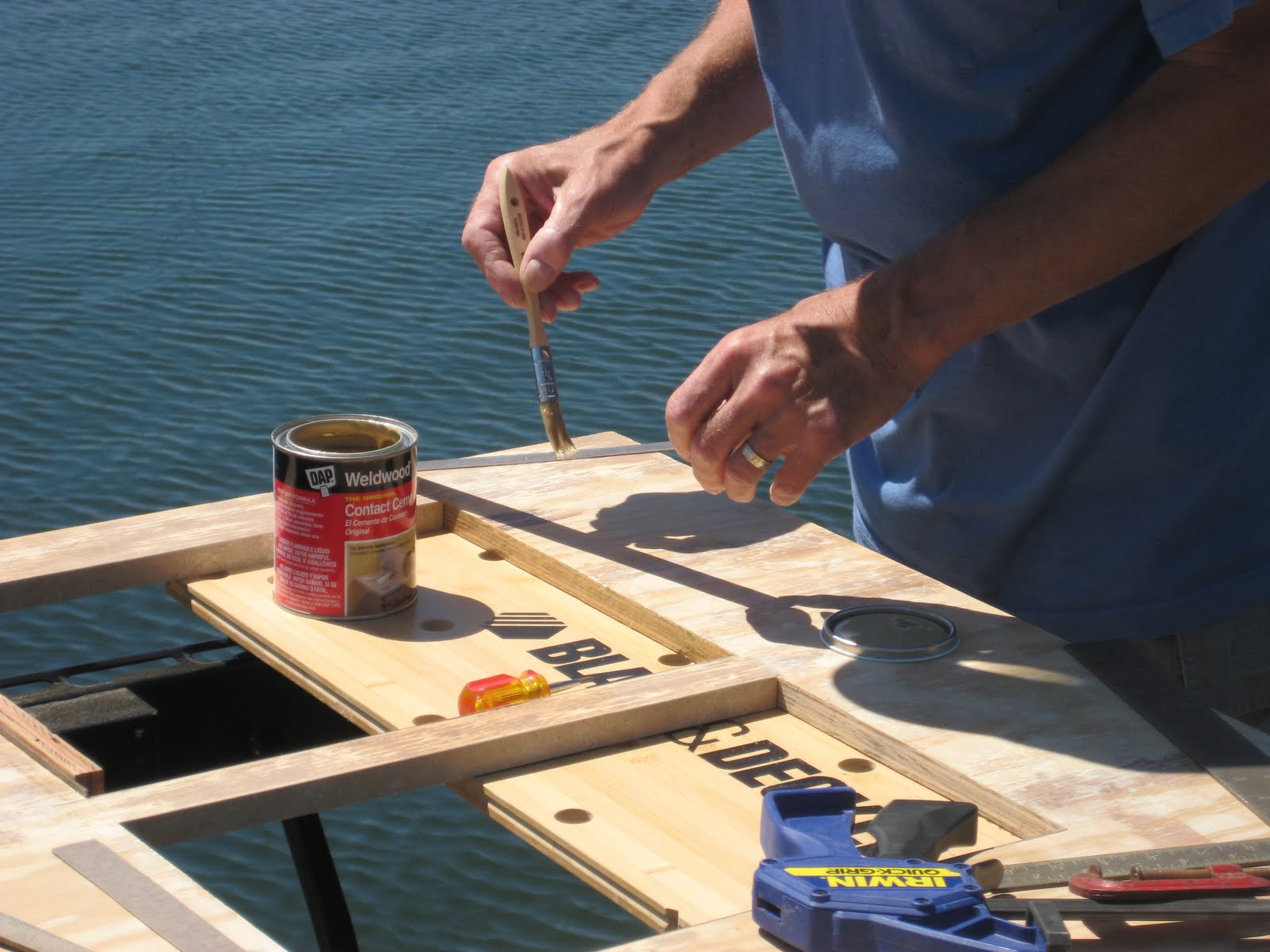
We looked at Wilson Art and Formica laminates and finally chose a Travertine design in Formica. Here we are putting the first strips around the edges of the two access apertures.

Close-up shot of finished edge trim after routing.

Here is the counter-top going in for another trial fit after the laminate was glued on.
At this point we started to build two brand new insulated access hatch covers. This wasn't in the plan at first. Our original design re-used two of the existing four factory covers, re-located to suit our new counter layout. Unfortunately, mid-way through building the new counter-top we realised that if we went that way we wouldn't be able to remove the big holding plate for repair, if necessary. When installed singly, the old hatch covers were too small to allow removal of the holding plate......that little oversight added a full week of extra work to the project..........sigh!

To make the new hatch covers we went with half inch plywood edged with oak to give us a little more room for the 2 inch insulation.
Another shot of an epoxied hatch being clamped up in the Workmate. (Love that Workmate....even though it isn't as rugged as the original design. It can be set up in the cockpit and also be stowed fairly easily)

We used small (1/2 x 3/4) extruded aluminum angle to support the hatch covers. This shot shows the angle being cut in the miter box.

Here we are drilling holes to secure the the angle.

Support cleat being installed. Note small pieces of the sealing strip temporarily applied to set correct cleat position.

First set of cleat angles in place.

Hatch covers in place......almost professional looking huh!

Now we need some insulation on those lids. We had no more of the 2" Thermasheath left but did have some of the 1" Insulfoam so we laminated two thicknesses of that together and used it instead.

Here we are trimming an angle on the lid insulation.

Ready for covering with some of the same liner panel material we used in the main fridge and freezer boxes.

Some of the liner panel material glued onto the sides, waiting for the 'top' to be covered.

Before the insulation is bonded to the hatch we needed to install the finger pulls.

What a fiddly job the finger pulls were! Dremel to the rescue once more!

Here is one of the finished hatches, from the bottom.


Finally........onto the home stretch, hatches and counter installed....Yeah!
The new counter shows up the rest of the galley so now we have to start varnishing and oiling all the trim and surrounding cabinetry! The rest of the galley counter-top areas will get the same Travertine treatment when we install the new stove and sink that we are getting.
After playing around for a couple of days with both the size of the choke in the freezer air drain and the thermostat setting we got the fridge to hold at about 36 F with the freezer set at around 16 F. The system seems pretty stable, with the compressor cycling for an hour or so a couple of times per day, so the insulation seems to be doing it's job. A digital thermostat is still in the plan to cut compressor run time even more but, for now, everything seems OK (fingers & everything else crossed).

The fridge is plenty big enough for our needs, although we are still working on our loading technique!

The freezer is a bit small but seems to have enough capacity for us. We have ordered a vertical ice cube tray so that we can make some ice cubes for our G & T's.....or should that be G's and T?
UPDATE 12-13-2012
Despite our initial confidence in the stability of the system, after living with it for several months we noticed it was very difficult to find a 'sweet spot' for the temperature setting. We were constantly fussing with the thermostat and the drain hole choke but the fridge side was always either too cold or too warm, no matter what we did. We had always planned for a digital thermostat in the system but before we splashed out for one we wanted to make sure the airflow through the system was working correctly. The dimensions and location of the drain and spill-over air holes in the divider had always been a bit of an educated guess......not very scientific....and they'd never been verified.
R.jpg)
Our first thought was that maybe the divider design was flawed and the spill-over air circulation between the freezer and fridge sides wasn't consistent so we tried using a small fan to help things along.
R.jpg)
We tried the fan in several different locations but quickly discovered that rather than helping things, the fan was actually aggravating the problem by disrupting the natural convection cycle. Back to Plan A, check the thermostat.
R.jpg) After spending a week accurately tracking temperatures and compressor cycle frequency we discovered that as well as the analogue thermostat adjustments being extremely vague, it had a lot of hysteresis, or lag. After making an adjustment and waiting for the compressor to activate, the temperature would have changed significantly, up to as much as 10 degrees. Similarly, when the compressor turned off, there was another long delay before the thermostat registered the new temperature. Much more precise control was needed.
After spending a week accurately tracking temperatures and compressor cycle frequency we discovered that as well as the analogue thermostat adjustments being extremely vague, it had a lot of hysteresis, or lag. After making an adjustment and waiting for the compressor to activate, the temperature would have changed significantly, up to as much as 10 degrees. Similarly, when the compressor turned off, there was another long delay before the thermostat registered the new temperature. Much more precise control was needed.

We decided to bite the bullet and replace the analogue thermostat with a digital one. After some research we got a digital conversion kit from an outfit called R Parts. It was a bit pricey but it is specifically designed for the Danfoss BD 35 and BD 50 compressors. Our Technautics Cool Blue system is powered by a BD 35.
R.jpg)
The installation and programming was very easy thanks to a comprehensive manual with clear instructions and photos. Our only deviation from the R Parts installation recommendations was to put the Carel controller in a separate surface mounted box rather than recessing it into existing cabinetry. We located the box against the bulkhead just above the freezer.
The new thermostat immediately made the difference between night and day. The Carel controller operates instantaneously at the programmed on/off set points and the the system temperature is very stable. The compressor cycle frequency has dropped significantly, it only runs for 30 minutes three or four times a day, and that has helped with power management when we are away from the dock. Bottom line is that the conversion was a very worthwhile upgrade.

Before the insulation is bonded to the hatch we needed to install the finger pulls.

What a fiddly job the finger pulls were! Dremel to the rescue once more!

Here is one of the finished hatches, from the bottom.

And from the top.

Finally........onto the home stretch, hatches and counter installed....Yeah!
The new counter shows up the rest of the galley so now we have to start varnishing and oiling all the trim and surrounding cabinetry! The rest of the galley counter-top areas will get the same Travertine treatment when we install the new stove and sink that we are getting.

The fridge is plenty big enough for our needs, although we are still working on our loading technique!

The freezer is a bit small but seems to have enough capacity for us. We have ordered a vertical ice cube tray so that we can make some ice cubes for our G & T's.....or should that be G's and T?
UPDATE 12-13-2012
Despite our initial confidence in the stability of the system, after living with it for several months we noticed it was very difficult to find a 'sweet spot' for the temperature setting. We were constantly fussing with the thermostat and the drain hole choke but the fridge side was always either too cold or too warm, no matter what we did. We had always planned for a digital thermostat in the system but before we splashed out for one we wanted to make sure the airflow through the system was working correctly. The dimensions and location of the drain and spill-over air holes in the divider had always been a bit of an educated guess......not very scientific....and they'd never been verified.
R.jpg)
Our first thought was that maybe the divider design was flawed and the spill-over air circulation between the freezer and fridge sides wasn't consistent so we tried using a small fan to help things along.
R.jpg)
We tried the fan in several different locations but quickly discovered that rather than helping things, the fan was actually aggravating the problem by disrupting the natural convection cycle. Back to Plan A, check the thermostat.
R.jpg)

We decided to bite the bullet and replace the analogue thermostat with a digital one. After some research we got a digital conversion kit from an outfit called R Parts. It was a bit pricey but it is specifically designed for the Danfoss BD 35 and BD 50 compressors. Our Technautics Cool Blue system is powered by a BD 35.
R.jpg)
The installation and programming was very easy thanks to a comprehensive manual with clear instructions and photos. Our only deviation from the R Parts installation recommendations was to put the Carel controller in a separate surface mounted box rather than recessing it into existing cabinetry. We located the box against the bulkhead just above the freezer.
The new thermostat immediately made the difference between night and day. The Carel controller operates instantaneously at the programmed on/off set points and the the system temperature is very stable. The compressor cycle frequency has dropped significantly, it only runs for 30 minutes three or four times a day, and that has helped with power management when we are away from the dock. Bottom line is that the conversion was a very worthwhile upgrade.