The Old Matelot


matelot;
noun,
sailor; from the French mat-el-oh (plural matelots)
A slang expression, chiefly in Britain, may also mean mate or companion.

Welcome to the Old Matelots' blog, my first (and probably last!) journalistic endeavour. Watch its development and evolution as I make the transition into retirement and the live-aboard, off the grid lifestyle on the sailing yacht, Circe. Follow my fortunes (and misfortunes) in the posts as I work to rehabilitate my home on the water.

UPDATE - Due major back-to-back relationship and health issues during 2017 & 2018 I was involuntarily beached and forced to let Circe go. The blog will remain up for the foreseeable future for informational benefit to other owners of these magnificent boats.


*******************************************************************************************************************************************************************


Showing posts with label Electrical. Show all posts

2013-05-04

AC/DC Panels

When we first got Circe the surveyor noted some issues with a few of the DC circuit breakers. They were the old thermal push button style and several of them were tripping randomly, even with no overload condition. Nearly all of the breakers appeared to be original and had probably long exceeded their lifetime switching-cycle rating. We replaced all of them with new ETA units from Allied Electronics and solved the immediate problem, but then we started planning to build a new console with new AC and DC panels, upgraded toggle style, thermal/magnetic breakers and LED status lamps. That part of the project has finally made it to the top of 'The List'!

We had been 'sneaking up' on this project for more than a year by doing other electrical upgrades in preparation. We had already eliminated the original analog Ammeter and Voltmeter and replaced them with a LinkLITE  monitor and Blue Seas smart relay. We also replaced the original Heart 1000W inverter/charger with a Sterling Combi 2500W, true sine wave unit. We ditched the telephone jack and temporarily mounted the Superwind control switch where the phone jack had been (The Superwind control will move into the new console when it is built).  We also cleaned up a lot of the wiring runs, replaced some wires and pulled out several that weren't functional. We had done the prep work, now it was time for the 'main event'! 

A shot of the factory original AC panel (left), DC panels (centre) and the monitoring panel (right), which is semi-redundant since we installed the LinkLITE monitor and bypassed the ammeter and voltmeterWe will reorganise the space, relocate the 110 VAC outlet and the wind generator control and improve access to the panel wiring by having the console hinge forward into the nav station. The propane control and charger/inverter control will stay where they are.


View from the back. The wiring was a mess, with numerous badly executed PO additions and alterations grafted onto the original rough and ready factory job


Accessing the back of the factory panels means emptying the starboard cockpit locker and climbing inside! A pain in the butt... both literally and metaphorically! There was an acrylic cover across the back of the panels designed to shield the panels from the contents of the locker, but it was a flimsy set-up. When the new console and panels are installed we will close off this whole area with plywood covers, fully isolating critical electrics from the locker contents.


We had already bought new Blue Seas AC and DC panels, some extra breakers, buss bars, wire and terminal strips. The only big thing left was to design and build a new, hinged console.


To get as much easy access as possible to the panel components we wanted a stand-off design that could be opened into the nav station. We had some strips of mahogany left over from repairing the wood rot during the Bomon Window project, so we had it ripped down and a dado cut to make the step frame for the new console. Here we are cutting the mitres for the corners of the frame. 


The frame sides are clamped, glued and cross screwed. 


Stand-off frame assembled, hinges fitted, ready for finishing.


The original plan for the faceplate was to use two pieces of 1/4" plywood, epoxy laminated together, stained and oiled to match the rest of the lower nav station bulkhead. But the more we worked on it the more chipping problems we had! Even with the 'good' side taped while cutting the apertures for the Blue Seas panels we still had chips. It was obviously crappy plywood. In the end we opted to fill the chips and paint the faceplate to match the upper bulkhead!


First test fit of the new panels. So far so good.


Here is the frame with some stain on it. We slapped the stain on to see how it compared with the surrounding nav station woodwork before we finished the frame and varnished it. 


Not perfect but close  enough for this good old boat! A couple more coats of varnish and we'll call it good.


Here we've got some surfacing primer on the face plate. We used wood filler first to repair the worst of the chips and splits and are hoping the primer will camouflage the repairs. The apertures, R to L, are for DC panel, AC panel, LinkLite monitor, Superwind control and a 12v accessory outlet. We left room for some switchgear expansion, but none is planned at present. Both AC and DC panels  have spare breakers if we need them.


The colour coat looks pretty good and hides most of the flaws in the wood. Time to assemble everything.


Looks pretty good for an amateur job, even if we say so ourselves. Next step is to start hooking up some wires.


We made two short looms for the DC panel, numbered all the wires and spiral wrapped them to keep things sanitary.


We decided to use terminal strips to provide an neat and easy way of  joining the existing boat wiring harness into the new DC distribution panels. We also numbered all the terminals with a plan to eventually have an accurate schematic for the whole electrical system..


Another view of the terminal strips. They are temporarily attached to an old piece of teak for ease of wiring.


The next step was to number all the existing 'boat side' wiring to match the new breaker numbers to ease the transfer of wires to the new terminal blocks. Then we carefully slid the old panels back through the bulkhead so we could keep power on while installing the new console. We turned all the power off while we squeezed the panels through the slot in the bulkhead and managed it with only two connections damaged...!


OK, OK...we know it was a bit dodgy, keeping all the power turned on while the panels are 'free floating' in the locker, but when you are a liveaboard the alternative is to move ashore until the project is finished! We wedged some lifejackets under the panels to avoid shorts and minimise strain on the wires and we did turn everything off at the main battery switch and dock box breaker for the two nights we were working on wiring.


Here we have mounted the frame for the new console and marked the area to be cut out of the bulkhead to accommodate the new panels and other components. The 110V outlet has been removed, it will be relocated outside the console where the old telephone jack used to be.


In this one we have opened up the aperture in the bulkhead and assembled the new faceplate and panels. All ready to start wiring things up.


At this point we brought in some professional help in the form of Earl Mathiesen of Mathiesen Marine to make sure all the circuit hook ups were done to ABYC standards. We also had Earl install a galvanic isolator, some heavier triplex cable between the 110V shore power socket and the new breaker panel and re-configure and consolidate all the hot and neg cables....they were jumpered all over the place around the old panels. 


New terminal strips in place ready to start re-connecting things......Spaghetti anyone?


Old panels on the way to the dumpster.


From chaos comes order. It took Earl several hours to go through all the various circuits and re-route everything, and our pre-numbering helped a lot. We had only missed one wire, and that was quickly identified as the power to the propane solenoid. Earl also changed most of the ground returns to bring things in line with prevailing ABYC standards.


Here are the results of Earl's efforts. A look back at the #2 picture in this post really tells the story. 


Not only neat, tidy and safe but also very accessible. After backing off three screws the new panel hinges down from the console and everything is easy to work on from the comfort of the nav station.....no more emptying the cockpit locker and 'cave crouching'. 


For once everything came together as planned and we ended up with a nice, ABYC compliant, electrical distribution system that isn't a hazardous embarrassment. We have updated components, spare circuits, better ergonomics, provision for safe input from the Honda genset and room to expand switchgear as needed.

On to the next project!


UPDATE 07-11-13

After several distractions we finally got around to scrapping the old acrylic protective shield behind the new console and installing some custom panels. They are made from 1/4" Hydratek on a simple frame of 1 1/2" x 3/4".


Inside shot from nav station.


Looking from inside the stbd cockpit locker. The cover panels can be easily removed if necessary and the two piece design makes them smaller and more manageable than one big cover.


The new panels also give us a convenient place to hang lines and the the genset input cord.


2012-08-16

Helm Instruments

One of the negotiating points in our purchase of Circe was that she was a bit skinny in the navigation electronics and instruments department. Apart from the original Standard Horizon depth sounder (working), Datamarine knotmeter (rarely working) and 5" Danforth Constellation compass (in need of adjustment) at the helm she only had a masthead Windex and a small Garmin GPSMap 130 located at the nav station. An old Autohelm wheel pilot (occasionally working) was also fitted, with the control head mounted inconveniently, across the cockpit, on the starboard cabin wall. A marginal instrument suite, adequate for local Bay Area sailing but not for voyaging, it had to be upgraded.


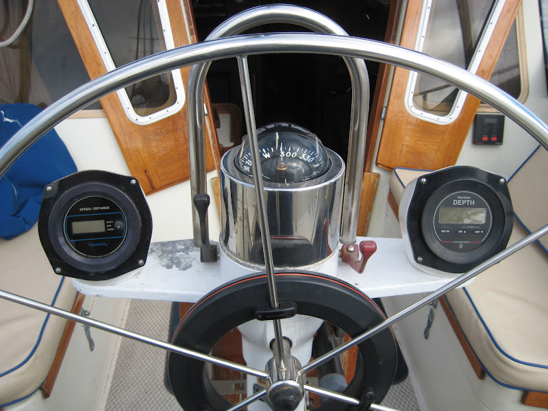
View of Circe's helm and instrument set up when we took ownership. Danforth compass flanked by depth sounder (R) and knotmeter (L) with autopilot drive clamped on the wheel. Also visible are the autopilot control on the cabin wall and the cheesy original plastic throttle and shift levers.


The only other nav aid on the boat was an old (c1996) Garmin plotter at the nav station. It worked perfectly but had very limited features and the tiny 2.5" x 3.5" screen was far too small for aging Old Matelot eyeballs, even with our 1.75x power Dr. Dean's!


The depth sounder also worked well but the control head was very large and clunky, filling an Edson pod at the stbd side of the helm. The knotmeter control head filled a similar pod on the the port side, but that instrument was highly erratic and only worked for a short time after each hull cleaning. After that the 'flora and fauna' growing on the hull stopped the little impeller in the sending unit from turning freely so the speed/distance readings became totally inaccurate or the unit completely stopped working. It was too much mess and trouble to pull the sending unit out after every trip, like some racers do, so we decided to deep six it and rely on the SOG info from our GPS units. We can't really see the point of admiring our sail trim and watching 6.5 on a knotmeter while the GPS is showing 3.5 SOG because we were heading against a flood tide? If worst comes to worst and all the electronics die, and we need to start deduced reckoning, we'll hang our Knotstick over the side, it's probably more accurate than any knotmeter!


Another view of the original helm set-up, this time from the companionway showing the 7/8" tubular pedestal guard and folding  teak cockpit table.


Our upgrade plan called for installation of a new Raymarine c127 big screen chart plotter and radar combo at the helm, with a wind instrument and possibly an underdeck autopilot to follow, as funds allow.


A previous post described the installation of Questus self leveling pole to carry our new Raymarine radome. This post describes the installation of the c127 multi function display at the helm. Our old Garmin plotter will stay at the nav station as first back-up (with a pair of 3x power reading glasses close by...he he!) and our Lowrance hand-held GPS unit will move from first back-up to second back-up and ditch bag. The old cantilever Edson pods will be replaced by a NavPod GP 1170 unit mounted centrally on a new, taller, angled, pedestal guard with bigger (1.25" dia.) tubes to accommodate the extra wiring for the new radar and instruments. (We initially planned to get a Scan Strut pod, as we think they are better built and have more versatile mounts, but at the time we were looking to buy they didn't have anything big enough to do what we wanted) Finally, we also wanted to replace the cheesy plastic throttle and shift levers and replace the compass lights with LED's. OK, time to start the tear down!


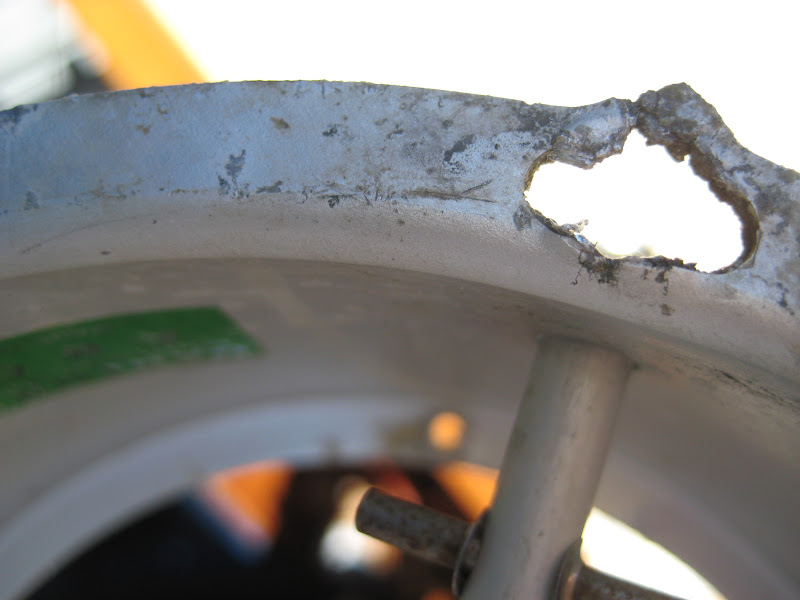
The compass, with aluminium mount and stainless trim sleeve removed. The mount was badly corroded at the mounting flange.


A combination of over tightening and galvanic corrosion had destroyed the adjusting slots in the aluminium compass mount. After lots of research and a call to Viking the compass 'go to' guys, we learned that new mounts for the 5" Danforth aren't available so we will have to re-drill the pedestal or come up with some other creative solution to re-install it.


Ready to pull the engine controls and Autopilot.


The old plastic control levers were still functional but they flexed a lot in use, particularly the shifter. They had to go!


Old and new throttle and shift levers. Note the retainer screw on the throttle shaft (r). It was stripped and re-drilled sometime in the past. A heli-coil in the original hole would have been a cleaner fix, but it seems to work okay with no side lash on the shaft, so we left it alone.


Wheel and autopilot off, depth sounder off and knotmeter ready to be removed.


The old pod bracket and the rats nest of wire in the pedestal will all go away. New cables will be routed through the new pedestal guard. Other than the short 6" pigtail for the compass lights, there was no twisted pair in the old power supply wiring to minimise EMF influence on the compass!


Hope it all goes back together as quickly as it came apart!


The larger, 1.250" diameter pedestal guard tubes required a new stainless yoke to replace the old cast alloy bracket and.........


.........also new stainless feet. The pad eye on the cockpit floor is for the helmsman to clip to in rough weather.


Here is the new pedestal guard in place, ready for the Navpod.


To solve the problem of the destroyed slots in the compass mount we cut out the corroded metal and opened the slots up. This is the 'before' shot and.......


.......this is what the slots looked like after surgery.


Then we took a couple of stainless fender washers, cut some slices off them and drilled the segments to suit the compass mount screws.


Then we slathered Denso paste over everything to stop further corrosion. It wasn't the most elegant solution but it worked well enough. We'll keep scouring the swap meets for a replacement 5" compass mount.


We looked for suitable 'plug & play' LED's to replace the compass illuminating mini lamps, but couldn't find anything that would easily fit into the mounting clips in the Danforth lamp hood. So, with the help of a neighbour who is an electronics engineer, we decided to build our own lamps.


We found LED's and resistors at a local electronics store, soldered them together and potted them into empty crimp fitting sleeves. By pulling the innards out of some #12/14 female disconnect fittings we got a perfect fit into the clips in the existing lamp hood. Not a great photo but you get the idea.


The new LED wiring is a bit cramped in the lamp hood, but there is enough clearance, just!


We selected LED's that would give plenty of light. We are building a dimmer for the circuit to adjust for various conditions. The bright reflections at 20 deg. and 300 deg. were because the lamp hood was just lying in place and not fastened when this shot was taken.


With the compass back in place we temporarily taped the NavPod in place. The radar chart plotter combo unit will go on one side, with space for an i70 wind instrument and the control head for a 'tbd' autopilot  on the other side.


Once we established the best position for the pod we taped the pedestal guard tubes, used the pod as a template, and marked the mounting and wiring holes. Using a succession of cobalt drill bits, the drilling and tapping of the four 5/16" mounting holes went quickly and easily.


Cutting the wiring holes proved to be more of a challenge! We were told by someone who recently did a similar job that a good quality hole saw would easily cut the stainless tube. We were a bit sceptical but decided to give it a go. We bought the best Milwaukee hole saw we could find and.........


........immediately destroyed it! Our helpful adviser neglected to tell us that in stainless steel this was a 'one hole per saw' job, even with a fine tooth saw at slow speed. Here is the saw after we got through the first tube!! Back to the store for another saw.


After modifying our cutting technique, based on our experience with the first hole, the second hole went a lot easier. We used the Dremel with sanding sleeves fitted to polish all the rough edges off  the wiring holes.Then we fitted the sealing strips and.........


.........then mounted the pod.


The next step was to cut the aperture in the pod face for the multi-function display unit. Once again we went back to the excellent Compass Marine site, where there are some useful tips on all sorts of  DIY boat topics. We followed all their recommendations on cutting pods and, although it was a bit stressful hacking into a brand new $400 pod, the results were pretty good, even if we say so ourselves!

Note: The recommendation from Compass Marine to go for a pre-cut pod if possible is very good advice for a low stress installation. Unfortunately, the pod we chose wasn't available pre-cut so we had to go the 'white knuckle' route.


The face of the pod cover has been covered with tape and the Raymarine template (paper) has been re-printed onto heavy card stock and also taped in place.


Here we have the hole saw pilot holes drilled with a brad point drill bit, clean and accurate.


Because our jig saw is a well worn antique we elected to use a hand saw to cut the outline of the aperture. It was slow going (+/- 20 mins per side) but we felt it was safer than using the jig saw, with less chance of straying from the template lines. For our troubles we were rewarded with nice clean edges all round.


Not only clean but also accurate. The c127 MFD fitted the aperture perfectly, with very little  clean-up sanding necessary on the edges.


The final result, not bad for a dockside job done in 18 kts of wind! The spare real estate on the stbd side of the pod will house the new wind and autopilot units that will be fitted as time and the budget allow. Now, time to pull some wires.


At this stage, because all the hardware involved was a bit on the pricey side, and we didn't want to make an expen$ive mistake, we hired Earl Mathiesen of Mathiesen Marine to supervise and assist with all the final radar cable hook ups, give us a tutorial on the system and generally keep us out of trouble. Earl also installed the new 'glue in' depth sounder transducer for us.


To help make the installation more sanitary we made and hung a simple strap bracket between two of the pod securing screws and mounted a small buss block on it for power distribution to the c127, as well as the planned future instruments.


We also installed in the bottom of the pod the dimmer we built for the compass LED illumination lamps. This shot shows the dimmer pot next to the RAM socket for the Standard Horizon VHF radio.


Here is the RAM for the GX 2150 VHF, mounted within easy reach on the stbd side of the pod.


Outside view of the dimmer knob and RAM socket.


This shot shows the effect of the LED dimmer at full range and.......


.......this one shows it almost fully dialed down. A nice wide range between the two extremes should be adequate for most night conditions.


Here is a look at the final wiring installation.


Helmsman's eye view. Compare with the first photo in this post. Need to save our $$ now so we can fill that empty space to the right of the MFD with wind and autopilot control head!


View from the companionway. Because of the larger diameter pedestal guard tubes we need to get new mounting brackets before we can re-install the cockpit table.


The last thing we need to do to is have a new helm cover made to accommodate the taller guard. It's on 'The List' but waaayyyyy down!

Addendum 8/18/2012
After the installation of the c-127 system went so well we should have realised there would be payback. There was! After firing up the system and playing with the display and menus for a couple of hours we powered down the display unit for the evening. The next morning we powered it back up only to discover that the system wouldn't recognise the depth transducer! After fussing with the set-up menus for a while and re-booting the system a couple of times, we made some phone calls. Imagine our surprise and  aggravation to learn that our brand new system had software (v2.10) that was at least two generations older than the latest offering (v3.15). Why so many upgrades to a product that was only recently introduced you ask? We did too. The answer: to address several problems including....you guessed it....the depth/fish finder feature.


We had to go and buy a new micro SD card, download the v3.15 upgrade directly from Raymarine, install it and then reset the whole system. Not a very inspiring start to our first experience with Raymarine products.

Addendum 1/10/2013


What is wrong with this picture?

Sorry, but there aren't any prizes for noticing our shiny new Raymarine digital radome is missing from its assigned position atop the Questus self leveling radar pole! Where is it.....on its way to Raymarine's service department for diagnosis and repair.

After the initial problems experienced with the out of date MFD software and the depth sounder/fish finder function (detailed above) the chartplotter and radar systems have both worked well with no problems...until the beginning of last December when the radar failed. There were no warning symptoms, the radar just quit working. The rest of the system; plotter, AIS, depth sounder all booted up but the system wouldn't recognise the radar. 


When we first booted the MFD the radar array icon was grayed out and the notation 'No Radar' was displayed. 


Despite the No Radar icon, a pop up box was simultaneously displayed indicating that the radar could be switched on by using either the menu box or the MFD power switch.


 We tried to power up the radar through the MFD power switch and the menu box and........ 


......while the system indicated it was connecting to the radar, after a few seconds........


........yet another box appeared, indicating the absence of radar!


At that point, additional trouble shooting was beyond our pay grade so we got some help from Earl Mathiesen at Mathiesen Marine. He checked out the whole system and determined that we had some kind of component failure in the radome. We pulled it off and sent it to Raymarine for repair under warranty. 


The radome was returned with a report that the IF card had been replaced and the system extensively tested.


Before we remounted the radome we added some bird spikes to discourage gulls that have recently added it to their list of 'must visit' perches in the marina.


So, once again we are back in business...Oh, almost forgot, the system software was again updated.....yes, another three generations of 'improvements' have been issued in the 18 months since we first installed the c-127!


To say we are very upset to have experienced a second major problem with an almost new system would be a huge understatement! Only time will tell if our decision to go 'all-in' with Raymarine for our nav requirements was smart or otherwise. We have a considerable chunk of change invested, so we're keeping our fingers crossed!

Addendum 1/16/2017

A rather belated update on the status of our our helm and navigation instrument upgrade. Somehow the installation of the new autopilot and wind instrument didn't make it onto the blog....so here they are.


Despite our concern over the initial problems we experienced with the MFD and the radome, the system has proven to be stable and reliable thus far. We continue to monitor it closely. The deluge of software upgrades has slowed somewhat but they do keep showing up. Time will tell if this system will meet our expectations for the long haul.


We were finally able to round up the necessary $$ to get the i60 wind instrument and P70 autopilot control and have been enjoying the benefits of the completed, conversational system for over a year now.


Without doubt, the nicest feature is the ability to sync the system to our iPad via WiFi using the embedded 'RayControl'.


With Raycontrol we can operate the whole navigation system from anywhere on the boat. It is so nice to plan a trip, install way points, adjust routes etc. from the comfort of the couch or dinette.


We also got around to refitting the cockpit mini-table. New on 'the list' is a bigger folding table that will be more useful and functional. 


Last but not least we also splashed out for a full helm cover to protect things.